Audio Derived Hang AGC for Vintage Receivers
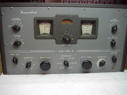
The radio on the left is a lot like my first HQ-129X. Mine also had a lot of wear on the volume control part of the panel, but not quite as much as this one. Mine had the tuning and bandspread knobs replaced, but was otherwise in original condition until I modified it to add an Audio Derived Hang AGC circuit. Mine was tube, but below it is also shown with semiconductors. If you ever try this mod. on a Hammarlund I'd like to hear about it. Email me at Curtis dot Eickerman (a) cox dot net .
QST Tube AGC
This circuit was originally in QST using a twin triode and a dual diode vacuum tube. I built the tube version and connected it to an HQ-129X similar to the one above. This made it possible to have AGC on sideband which is how I used the Hammarlund for many years along with an Apache TX-1 and SB-10. This was easy to connect, worked fine (there was no popping on initial sylables) and made the receiver a pleasure to use on sideband. See the top link for the design. For my implementation I used a 6AL5 and 12AU7. It was constucted in an external box along with a switch that allowed me to toggle between the original Manual condition in the BFO position and the AGC being enabled. This unit sat in a box on top of the radio. It was attached via a connector on the back (2 filament, 1-B+, 1 ground, 1 Audio and 1 AGC line).
Fortunately the original ground for the AVC line in the receiver did not connect directly to ground inside the shield can containing the Off/AVC/BFO switch. So it was just a matter of locating the wire under the chassis, disconnecting it from ground, splicing on some additional wire and routing it to the back panel of the radio inside the chassis.
Audio Hang AGC A
The second link is for a semiconductor version of the design with a simulation. The simulation shows how the AGC will "hang" with a low decay rate until until the hang time constant is exceeded. Then it will drop the AGC voltage at the higher rate. This keeps the AGC from pumping up and down between words or syllables, but drops off appropriately once speaking is discontinued (after about 1 second).
Audio Hang AGC B
The third link is a version that should have a higher input impedance. I always kind of wondered if the initial semiconductor design might "load" the detector excessively. Of course a simple JFET follower up front could eliminate loading concerns completely. For the transistors an NTE194 should be suitable. The 2N5550 was used because it was available in the simulation program.
HQ-160 AVC and S-Meter Enabled for SSB and CW
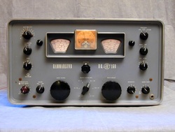
It is possible to modify the Hammarlund HQ-160 to have AVC and S-meter operation when operating SSB or CW by simply cutting two connections and adding a 3PDT switch with a resistor and capacitor.
You can fiddle with the cap value to get the specific performance you desire and it could be well worth the effort. You might try something like 0.1 uF for starters. It should have a relatively short charge with a longer decay. You should be able to go up on the value until the charge rate gets too slow and causes popping on the first syllable. If that isn't long enough for the decay rate then start increasing the 1M.
HQ-160 SSB AGC Mod
The HQ-160 has a product detector and can demodulate SSB well with the AGC enabled. Unfortunately Hammarlund chose to ground the AGC line and disable the S-meter when operating CW or SSB. This is changed by removing the ground and re-enabling the S-meter in the modification. Original operation can always be restored by switching the 3PDT switch back to the Manual position. The added resistor and capacitor are just provided to allow adjusting the AGC decay rate to better suit SSB communication.
Here is a link to the discussion where this modification was developed.
http://www.antiqueradios.com/forums/viewtopic.php?f=5&t=195258
SB-101 Modification
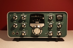
SB-101 Receiver Desensitization After Long Transmissions
There is a modification I made to my SB-101 that I have not found documented elsewhere. In a forum I did see someone complaining about the problem that I had encountered, but not the solution. Here is what happens.
After long transmissions, when returning to receive, the receiver seems to be desensitized and the S-meter hangs up . There is a recovery of 20 or 30 seconds as the receiver returns to normal and so does the S-meter. At first I thought it was something in the AGC itself, but that was not it.
What is really happening is that the receiver is actually receiving its own carrier oscillator leaking into the IF chain from V2 the 6AU6 Isolation Amplifier. However V2 is not the cause of the problem. The purpose of V2 is to cut the connection between the Balanced Modulator and V3 the 6AU6 First IF Amplifier when in the receive mode. V2 should cut this path effectively because when you are in receive mode it loses its 300 V plate voltage coming from pin 7 of relay RL-2. Or at least it is supposed to lose it. Pin 7 of RL-2 provides voltage to both the Isolation Amplifier and the 6146 screens when transmitting. However, on long transmissions something can happen to the 6146s that creates the problem.
Whatever you want to call it (grid emission, grid leakage, space charge, etc.), one or both of the 6146s can become a source of positive voltage after long transmissions. This appears to be dissipation related. So, after a long transmission this voltage source can be significant and actually supplies the Isolation Amplifier with plate voltage and causes it to "not isolate" after pin 7 of RL-2 has disconnected the 300 v line from the supply. As the 6146s cool down after the transmission is over this voltage decays and the Isolation Amplifier returns to its job of "isolating."
Changing 6146s might help. A fan might help. There are probably a lot of other things that might help, but I made a slight modification that eliminated the problem regardless of what the 6146s were doing. I simply inserted a diode just before the 100 ohm resistor that then feeds pin 4 (the screen grid) of the 6146s. The cathode points to the 100 ohm resistor and the anode points back to pin 7 of Rl-2. The end effect is that any positive source voltage from the 6146s is not allowed to feed back to pin 7 of the Isolation Amplifier and the problem goes away.
SB-101 Receiver Grid Leakage AGC Issue
Grid leakage problems also happen in the SB-101 AGC system. The factory modifications even say that tubes from certain manufacturers don't work well for exactly this reason. Where I experienced this was when attempting to use 6HS6 tubes for 6AU6 tubes at V10 and V11 (RF Amp and 1st Receive mixer). I loved the additional gain, especially on 10 meters, but after 15 or 20 minutes noticed the S-meter decay rate became very fast and the meter would decay below zero. This is caused by grid leakage or grid emissions from V10 and V11.
The leakage causes the AGC to not just leak to zero, but is now leaking toward the positive voltage being supplied by V10 and V11. This is what causes the faster decay rate and the zero shift. To put a stop to this I am contemplating a modification that I have not yet attempted.
Basically the modification would replace diode D101 with the Base-Emitter junction of a PNP transistor with a Vce rating of over 200 volts. The Base would connect where the cathode was, and the Emitter would connect to where the anode was. Then the Collector would connect to the negative bias supply of -130 V (I have not decided exactly where).
As a result the voltage at C124 no longer directly supplies the AGC voltage to everyone, but mostly just controls the voltage that this transistor delivers to the AGC line from the negative bias supply. There still will be some grid leakage effects but they should be greatly reduced by the beta of the transistor. Since a lot of PNP transistors with high Vce ratings don't have very high gain, it may be necessary to use two devices in a Darlington pair arrangement. What also I don't know is whether resistor R415 (1M) should also be reduced and , if so, to what value.
Theortetically this should make the AGC line relatively immune to grid leakage at V10 and V11 by simply supplying a lower impedance source of negative AGC voltage that prevents them from going positive. Then the receiver and AGC will behave normally even with leaky tubes anywhere along the AGC line.
Vintage Radios
This is a spot for stuff I have done for people on the Antique Radio Forums.
Temporary Location for Vintage Radio Dial Artwork or Schematics
Philco Dial Face 54-5069-1
Spartan Dial Face B1600-1
Airline Dial Face 112607
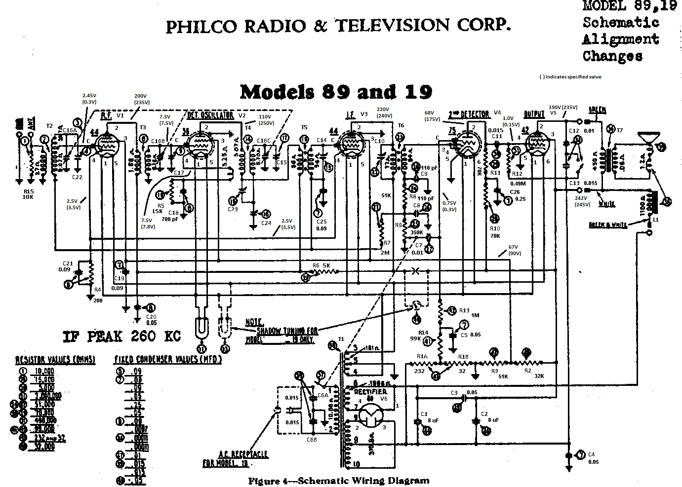
Philco 89 Schematic
Temporary Location for Vintage Radio Dial Artwork or Schematics
Philco Dial Face 54-5069-1
Spartan Dial Face B1600-1
Airline Dial Face 112607
Philco 89 Schematic
